I purchased a LoadCape from Mouser.com. I thought, ooh la la, another Cape to try out and make things transpire.
…
Onto the betterment of Cape works…exactly how does this Cape, the LoadCape, work? Do you have any schematics on this Cape?
I was just wondering.
…
Seth
P.S. I see there is a VIN and GND. This is good. I have some screw terminals for a battery supply. Now, these current sinks have fooled me so far. I keep getting stuck in high amounts of math w/out theory. Do you have any recommendations on what to research for this specific Cape, i.e the LoadCape?
The load pins simply connect one of the pins to ground. Say you have a giant LED that you want to control. You would connect the LED to whatever power source you need and then the second connection goes to ground through the load cape.
So, say Sink 1 on my LoadCape is GND? Now, I must attach power via some outer power source, i.e. not from the LoadCape? As you can tell. I am a bit confused on this event. Do I use the VIN as the power input source and skip the GND on the Cape b/c Sink 1 is now my GND?
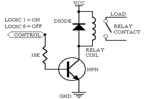
There are diodes to protect the circuit from inductive loads, like a relay or solenoid. The VIN pin can connect to the power source you have.
Say you have a 12V relay you want to control, GND goes to (-) and VIN goes to (+) on your power source. Now, the relay coil can connect to one of the Sink pins and to (+)
Search the web for “controlling a relay from amicrocontroller” and you will see things like this image.
Thank you. I have been reading up on how to control current sinks from microcontrollers. I think my search protocol was off. Thank you for the update and ideas.
Seth
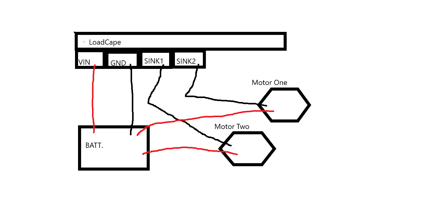
P.S. So, I just need, for a two-wire device, a four-wire connection, e.g. two positive and two negative (GND) leads ending in the Cape. If this sentence does not make sense. Please forgive me. I think I get it now.
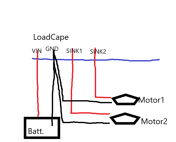
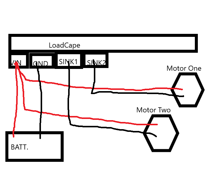
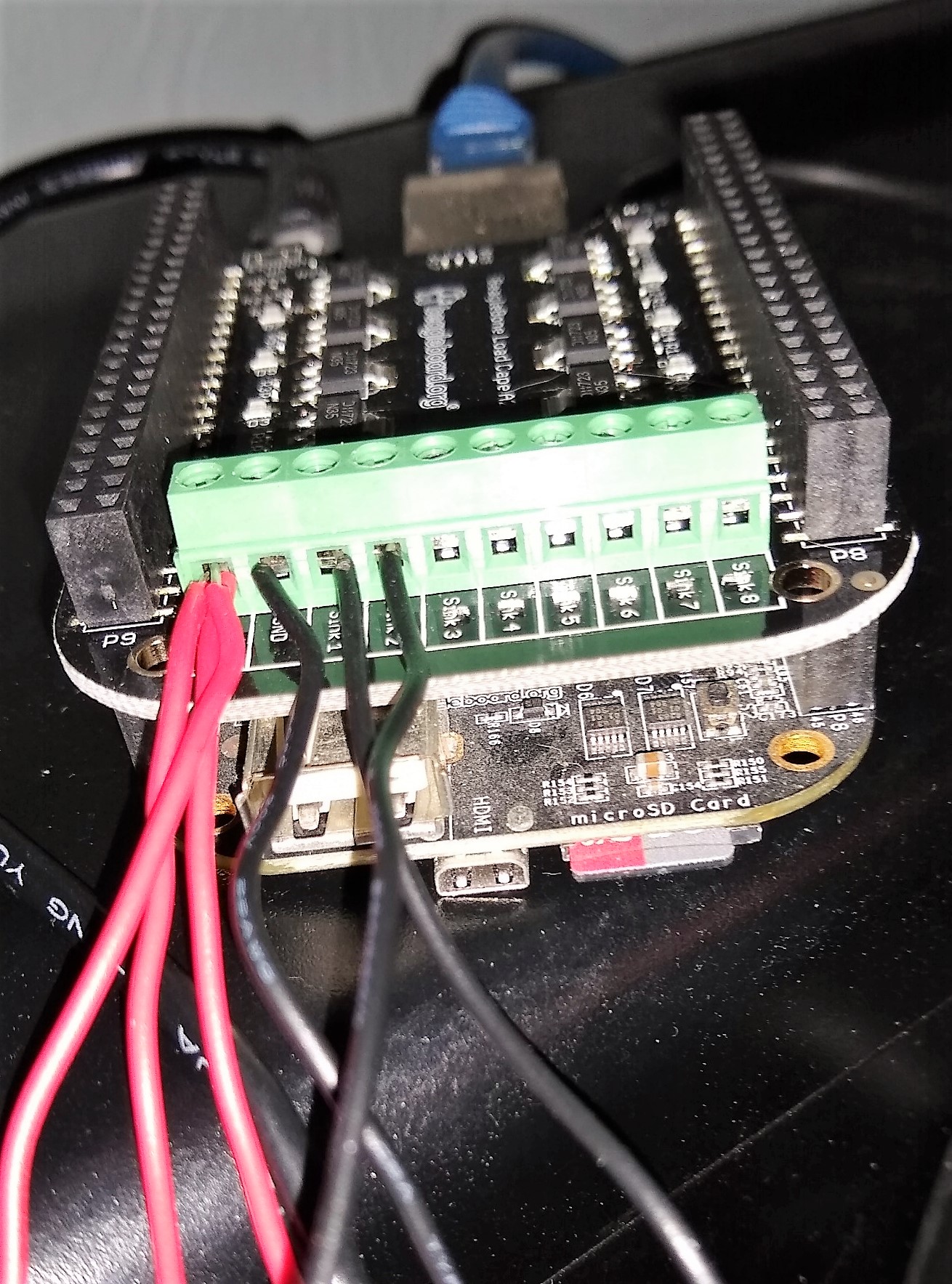
Just for the record, I tried the six wire set up in my photo I provided. I used the USB for communication w/ the battery plugged in at the same time.
…
My computer, desktop, notified me of the processor being ready for use, e.g. am335x. It did not signal that my BeagleBone was ready for use. Is this a complication people are seeing?
Seth
P.S. I think my set up is completely incorrect or I need to set up another route. Oh and my set up w/out the battery plugged in does not allow me to communicate w/ the BBB via USB. Is this odd?
I have had to flash my image again. The board just died from my set up that I mentioned in the above photo.
Seth
P.S. I will keep trying. Look, I know you all are very busy and do not have time to manually help each individual that has concerns w/ a current product. B/c of that idea, I am willing to wait for any support that is available. I will continue testing until I get this LoadCape up and running!