i’m trying to port TinyOS 0.60 on this board that i received yesterday
a cheap [STM32F407VGT6 (28 Mhz Crystal) Board]https://www.ebay.com/itm/STM32F407VGT6-ARM-Cortex-M4-32-bit-MCU-Core-Discovery-Development-Board-STM32F4-/112491161066?hash=item1a30fee5ea )
but i can not recognize USB OTG (seems no pullup there) for pins PA11, PA12
usb on the board do not start - and usb here more act as power supply only …
So what i need to do from changes something to make it usb recognised
here is board scheme i received from seller
Justin
November 22, 2017, 7:18pm
2
ST datasheet xtal specs are 4 - 26 MHz, maybe 28 MHz is the issue.
1 Like
If that i change it with an 8 or 12 or any close to thuse values which i can divide well mcu speed from 168
168 / 8 = 21xtal cycles
Hi guys
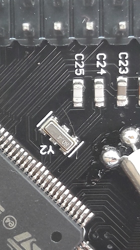
Can anyone identify this kind of xtal
Changed this Y2 to 12 Mhz but problem remain the same
Justin
November 28, 2017, 7:14pm
5
Have you pulled BOOT0 and BOOT1 low on J4 and J5?
1 Like
Did that mean boot0 and boot1 to connect to gnd for low
(sorry for questions i’m not electronics proficient - i am corporate win/web and db developer)
Justin
November 28, 2017, 8:19pm
7
Yes, for normal running both are pulled to gnd.
Brett
November 28, 2017, 9:28pm
8
So to be maybe a little more helpful, you would normally pull them to GND with a pulldown resistor, and you can pull them high with a jumper or button to VCC as needed, but since you have a commercial board you may not have that luxury, and you’ll have to bodge.
Based on this schematic
https://drive.google.com/file/d/1v6SOr5LdHAxZJ69R-qnMdQeNwIoRc46O/view
Which i received from seller pa11/pa12 is not pulled up and are connected directly tu mcu
But when i put an 22ohm resistor between 3.3v and pa12 to pullup D+ line now appear to device manager but as unrecognised usb device
on discovery vbus is connected to pa9 there in this board i have no vbus on pa9 or i need also to pullup and pa9 with 3.3v too.
Brett
November 28, 2017, 10:02pm
10
check Device Manager to see the VID and PID - if it is working at all it’ll report there ?
1 Like
Justin
November 28, 2017, 10:14pm
11
You dont actually need 22ohm resistors and you dont need to use PA9
There is obviously other fluff in the clack valve.
1 Like
seems board have problem so i did different tests:
vcc - gave me 5v
1.) i did blink sample on C++ nothing happen
2.) did all pin PD12,PD13,PD14,PD15 hight only - voltmeter show me 0v
but when i connect to SWDIO i can flash / erase memory / erase chip
I just picked up a couple of these micro’s from a local supplier. Did you get your port to work? I don’t have a board yet but plant o make something with them soon.
for that mcu tinyclros was ported without problem from nucleo-f401 porter
but i have problem with owned boards do not recognise dfu nor pa11/pa12 and boot sequences.
so i left shelf those no name boards.
here is latest TinyCLROS 0.11 - STM32F407 discovery (from some pice of source code take from CERB)
https://drive.google.com/drive/folders/1xYKVJ5LZBExmCMUCe85aQdlSFNmdxg8J?usp=sharing
but not tested since my boards do not work
1 Like
I’ll have a look at this after I have the board built and ready for testing.
Did anybody test that port?
