Hi!
Is it possible to generate more PWM output ports than the existing PWM1…5?
i need about eight PWMs and i have to use the ether shield…
thanks in advance,
mark
Hi!
Is it possible to generate more PWM output ports than the existing PWM1…5?
i need about eight PWMs and i have to use the ether shield…
thanks in advance,
mark
Hi Mark,
PWM pins are a limited resource, unfortunately. There are only 6 PWM capable pins on the processor that’s used on Panda2 (and on Domino for that matter). So you’re going to need to look at another option here - either a PWM capable chip, or even a DL40?
@ Mark15 - You can use OutputCompare and do software PWM on any pin.
Check this post
And search the forum/codeshare.
Thanx Architect,
‘OutputCompare.Set’ did the trick, i implemented that with the PWM over oc option - as described in the link you posted and https://www.ghielectronics.com/docs/18/pwm, example 6.
I’m using currently nine such PWM ports, each controlled in a seperate thread. The ocPorts drive MOSFETS over a small gate resistor an a pulldown resistor. Unfortunately when delivering new PWM values to these threads, the output has some flickering.
Is there a chance to see why it flickers?
thank you in advance,
mark
Is the flicker getting better when you use less then 9 oc/threads?
Yes, flickering/flashing depends on number of ocPorts and also PWM frequency
(at higher PWMfreqs (1k up) the panda dies and reboots too… I’m using 144Hz at the moment).
The OC.Set method and overloads are non-blocking methods. I wonder if you can work with less threads to limit context switching. I would try to work in that direction. It has hard to thing of anything else without seeing the actual code.
it’s not really clear for me why context switching causes OCports to change their state/signal on their own… could i lock the oc.set command for better results?
What you are probably seeing as flickering is the “upset” PWM pulse as you initiate a change. Do you have an oscilloscope? Check the waveform to validate that. If that’s true, since the Panda firmware is closed source, you would need to look at programming your own RLP to behave differently, if possible…
I see. This would go too deep, not my aim to do rlp. I just wondered if there is a way in managed code… i’lhave some tests later on.
Thanks architect&brett for your answers!
I do think its related to the pwm train being changed mid cycle, and a way to check that its not just threading interactions is to simplify your code and just use one pwm signal and see if your changes in cycle shows the same behaviour.
Perhaps you can also show a code and someone with a panda and an oscilloscope can test my theory more too 
i do not have a memory oszi. i tried to put all OCsets in one thread, tried to lock() OCset, not really getting better though, even worse…
The panda2 is several times in usage here for other issues (perfectly fitting!), so i guessed to take this cool thing also to manage a multi color daylight simulation with at least nine channels… obviously not the best choice for smooth transitions in parallel.
Any suggestions for an other affordable module to do this task? (RLP as last way out here for the panda, but i am affraid to not having enough memory for this)
What about using a TI TLC5940 pwm driver IC that communicates over SPI?
hi,
i have written a code for two pwm pins(D21,A1) of fez panda iii board with 0.5 duty.i have seen the two pulses in oscilloscope,both the pulses start at the same on time instant.i actually want second pulse to begin at the end of first pulse i.e. first pulse off time should be the on time of second pulse.is there a way to specify on time and off time for pwm pulse?
thank you
Usually you will get a faster response by starting a separate thread…
I believe that all the PWM outputs share a common clock, but can have different duty cycles.
But, could you use an inverter chip to derive the second output?
Agree with @mike. Better to start your own thread especially when your question is so unrelated to the original thread.
Also not aware of a simple way to phase shift two signals on the micro’s PWM peripherals. An inverter being driven from the same PWM pin should work (you could use a second signal but that’s not necessary).
@mike.@Brett. Thanks for the quick response.yes inverter chip would do the work for single phase but i am trying for three phase where i need three pulses with phase shift.
First you said two signals, now there are three. What exactly are you trying to implement?
i am designing a 3 phase inverter where i use pwm signals as control signals for switches.so totally i need six pulses in which three pulses with phase shift and the other three are invert of them.
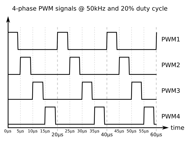
hi
i need pusle like in the picture .can you please tell me how i can get it through program??
thank you.