Alright guys…final stages of my design are almost complete. Just need to figure out the FT232R and also a battery supply.
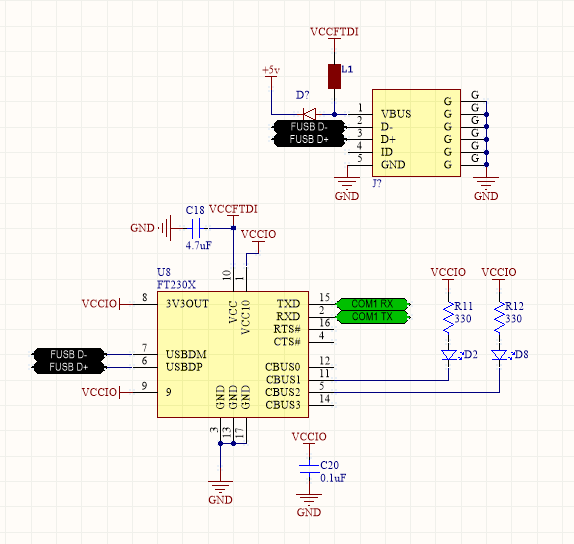
In the data sheet, for the UART microcontroller interface schematic, it shows the CBUS0 pin going from the FT232R to the microcontroller. The FT side is labeled Clock Out while the uC pin says Clock In. What pin would Clock In be on the G30? Is that the USB detect pin?
I am also unsure which CBUS0 option I should be using. I think the default mode is #PWREN
“Output is low after the device has been configured by USB, then high during USB suspending mode.”
Can someone please clarify what this means? I think it is saying after you set the baud rate, COM port, etc from the PC side, this pin goes low to confirm success. If USB communication is not possible, this pin goes high. Correct me if I am wrong please. Still not clear where this goes on the G30.
“clock out” and “clock in” aren’t UART specific pins for asynchronous serial - they’re typically only needed in synchronous serial like SPI. In the example in the datasheet, all they’re saying is that the FT232R is set up to output a clock to generate that for the micro - the G30 has different needs and you can safely ignore that. UART specific pins are TX, RX and if you really get fancy you’ll have hardware flow control with RTS and CTS pins (request to send, clear to send).
From the datasheet, CBUS3 is the default pin set up for PWREN function. “Default configuration of CBUS3 – Power enable. Low after USB enumeration, high during USB suspend mode”. This is a USB function, when you want to enable suspend mode - not a function of the GHI side of things. Your questions about FT232Rs in general are not going to be ones many people here are likely to have immediate answers to, only if you fluke someone who has done commercial integration work on that platform before. You may be better off asking FTDI for help
Ok thank you that answers my question …I was just making sure I can get away with only TX and RX because Fig 7.4 shows two CBUS pins going to the uC.
I think my only other question is in regards to the power circuit. Right now I have it wired exactly as Fig 7.4 shows, this draws 5 V from the USB bus. However, I think I need to use the self-powered configuration drawing from my board’s regulator. If anyone has experience with USB interfaces, any input would be appreciated. In the mean time, I will try to contact FTDI and see what they advise.
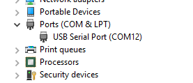
When I put all the same settings (baud rate, stop bits, etc) in the GUI settings as I have on my uC, clicking the open button fails and as does writing from uC to FT232 (gives me a SystemArgument Exception for the latter).
How should I be initiating the connection from the PC/USB side? Should I initiate the SerialPort() class on the PC first or the uC first?
Pin 1 on The FT232 (TX) is wired to RX and Pin 5 FT232 (RX) is wired to TX on the G30. I am using COM2 on the G30. Would I also input COM2 on that GUI? Or would it be just “2”? Or does a PC start at COM0?
The GUI says “Failed to open port, is it open in another application?”
Is the shield on the USB receptacle supposed to be grounded? I have the ground pin wired obviously but I am wondering if one of the prongs on the shield should be grounded?
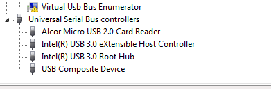
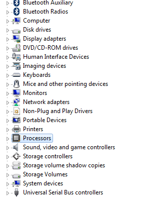
How can I tell if my USB port is 2.0 or 3.0? I think all of my desktop may be 3.0 because the G30 would not connect to it. There is 2 ports I am unsure of though. One has a lightning bolt next to the USB symbol and one has a plus symbol. The others are SS which is 3.0 I think.
Ok it may be the cable I am using…all I could find was a male to male that has a weird house shaped port on it running in parallel. Lol I have no idea what its called but its like a square with a trapezoid on top. I will go buy a straight male to male USB cable with nothing in parallel before I start picking apart my circuit.
you can’t plug the G30 development board in to 3.0!!! haven’t been able to code on my desktop (and have internet access) this entire project, have to use the old laptop.
FTDI says its a WIndows 7 / 3.0 compatibility issue.