Dear friends,
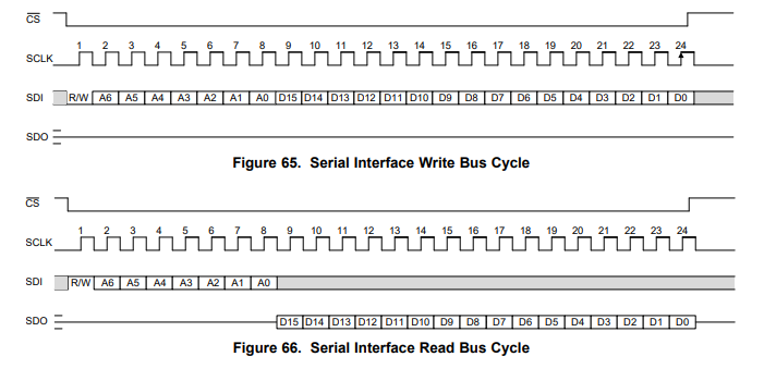
I need help with SPI. I’m trying to talk with a TI AMC7834 chip. Its data sheet says, " Each serial-interface access cycle is exactly 24 bits long. A frame is initiated by asserting the CS pin low. The frame ends when the CS pin is deasserted high. The first bit transferred is the R/W bit. The next 7 bits are the register address (128 addressable registers), and the remaining 16 bits are data. For all writes, data is clocked in on the rising edge of SCLK. If the write access is not equal to 24 clocks, the data bits are not committed. On a read access, data is clocked out on the falling edge of the serial interface clock, SCLK, on the SDO pin."
I am setting up the SPI port alike so:
SPI.Configuration spiConfig = new SPI.Configuration(
ChipSelect_Port: Pins.GPIO_PIN_D4, // Chip select is digital IO 4.
ChipSelect_ActiveState: false, // Chip select is active low.
ChipSelect_SetupTime: 0, // Amount of time between selection and the clock starting
ChipSelect_HoldTime: 0, // Amount of time the device must be active after the data has been read.
Clock_Edge: true, // Sample on the rising edge.
Clock_IdleState: true, // Clock is idle when high.
Clock_RateKHz: 2000, // 2MHz clock speed.
SPI_mod: SPI_Devices.SPI1 // Use SPI1
);
spi = new SPI(spiConfig);
I think that every transaction must be 24 bits long. So, if I want to send just one 8-bit byte, I should actually send it as a UInt16 (The register byte plus two UInt16 bytes makes three).
The trouble is, it doesn’t work. When I do a simple Write/Read to a stable register like VendorID, I only get zeros.
Maybe it has something to do with the last sentence from the data sheet… falling edge for read? Can anyone offer a suggestion please?
Thanks-
MRO
First I just want to say that a logic analyzer is an invaluable tool when debugging bus communications. Much like an oscilloscope, but with built in conveniences, it would show you exactly what is seen on the bus. Nothing makes it simpler to understand the problem.
My initial reaction is that your error may be in the UInt16 part.
I think CS is asserted and deasserted with every call to Write / WriteRead().
So if you are sending three bytes, and two of them are in a UInt16 then does that mean you are doing something like
SPIBus.Write(theVendorID) // write first byte

SPIBus.Write(Data) // Data is UInt16 so write two more bytes
That wont work if this is the case. Considering your own memory management techniques do something more like
byte theVendorID = (byte) someNumber;

theVendorID |= 0x80; // Set the R/W bit to 1

byte theData = (Uint16) someOtherNumber;

byte[] TX = new byte[3] { theVendorID, (byte)(theData >> 8), (byte)theData );

SPIBus.Write(TX);
This is assuming VendorID is the stable register you were talking about? It isn’t clear to me what you tried.
Some other things to consider are endian issues. Does the receiver think the data is invalid because each byte is backwards? ( 1 => 0b10000000 ) instead of (1 => 0b00000001)
Do both devices support the 200 MHz clockspeed?
Are you sure you wired the right bus? I think there’s an off-by-one thing where SPI_Devices.SPI1 is actually SPI0 in the processor’s documentation.
Dear JWizard -
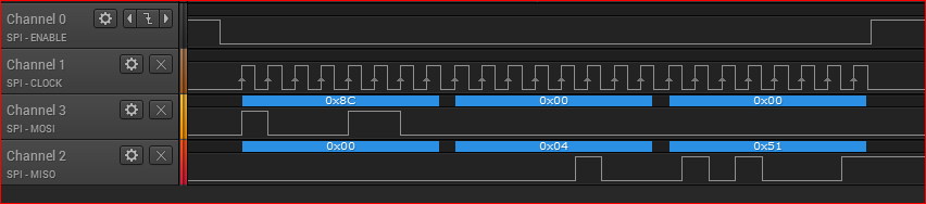
Thank you for the thoughtful reply. For clarification, the VendorID request is at register 0x0C. It should yield 0x0451 . The Microsoft.SPOT.Hardware SPI class offers a number of overloads for ReadWrite that take arguments such as ushort[] and byte[] so I’m pretty confident that they execute the ReadWrite in a single operation rather than breaking into individual Read and Write.
I tried various endian arrangement with no success… always returns zeros.
The clock speed is 2 MHz and both devices can do that.
The Netduino Plus 2 host that I am using only has SPI1 (no SPI0) and other examples seem to work all right with it. I’m going to track down a logic analyzer, roll up my sleeves, and dig into this more deeply.
Thanks again,
MRO
I really believe that no signature of ReadWrite will work for you other than one that uses byte[ ].
If you are breaking this into multiple calls I would be very surprised if the compiler knew you wanted a single transaction.
So you are probably using a single call to Write read. A few of the signatures will work for you. But if you use one that doesn’t use byte it is probably impossible to get a 24 clock period transaction, and then you are going to have to move things around because you stored your read across two array entries.
The datasheet says set R/W to 1 for reads. Data is MSB ordered.
UInt16 [ ] TX = {0x800C} ==>  RX[0] would have the first 8 bits stored in register 0 as it's last 8 bits

UInt16 [ ] TX = {0x8C00} ==> RX[0] would have the the first 8 bits stored at VendorID as it's last 8 bits
In both examples above the transaction was 16 clock periods…
UInt16 [ ] TX = {0x8C00, 0x0000} ==> RX[0] would have the first 8 bits stored at VendorID as it's last  8 bits
                                     RX[1] would have the  last 8 bits stored at VendorID as it's first 8 bits
This was a 32 clock pulse transaction. and then
UInt16 ReconstructedData = ( RX[0] << 8) + RX[1];
And hopefully the other device doesn’t mind that you are ignoring its transaction length guideline (requirement?) of 24 clock pulses.
Just use byte[ ] is all I’m saying here. You may have other issues as well, but without a doubt… byte [ ].
Just a few comments. You could (easily) bit-bang this to prove it works. That way you can prove you can talk to the thing, then you can make it work with SPI.
I also agree, 3x Byte is about the only way I see you getting this to work. And you’re possibly going to need to assemble your packets as you may struggle to get the structure right otherwise.
If I’m not mistaken here, he will need to send at least 4 bytes to get a response. The first byte sent will have the command to read or write, therefore the first byte he receives will be blank.
The datasheet is very clear that all transactions SHOULD be 24 bits and Write transactions MUST be 24 bits.
The settings you are using look to be correct. The mention of using UInt16 makes me think you are clocking too much / probably not sending the first byte that you think you are.
It does not say what will happen if you keep clocking after 24 in a read operation from what I read. It does say that a frame is over when CS is deasserted. So I assume it would recover no matter how long you clocked a read. The analyzer will tell you if you are deviating from this pattern. No point trying to deviate from this even for reads because you are just messing another unkown of how will it handle extra clocks.
Since it’s SPI I suspect that only the last 24 bits will remain in the shift register. So if you clock more than 24 then you start to loose the first bits.
Dear friends,
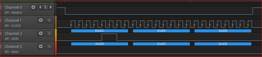
Thanks for all the suggestions. I borrowed a logic analyzer and found the problem… the Netduino Plus 2 (ver 4.3.2.1) implementation of SPI.WriteRead() wasn’t adding a Write bit for the supposed Write operation. For the following code:
byte[] WriteBuffer = new byte[3];
WriteBuffer[0] = Register.VendorID;
byte[] ReadBuffer = new byte[3];
spi.WriteRead(WriteBuffer, ReadBuffer);
0x0C is the VendorID register address. Notice that there is nothing in the MSB of the MOSI line.
OK, so I’ll provide the Write bit myself… change the 2nd line to
It’s a Saleae Logic 8 https://www.saleae.com
I have never used a logic analyzer before but I was up and running in five minutes. It’s great.
Best,
W9IP